


News and Information
What is Reflow Soldering? Principles & Applications in PCB Manufacturing
2025-12-11
Solder reflow is a leading critical soldering technology in modern PCB manufacturing processes. With its precise temperature control and high efficiency in mounting components onto printed circuit board surfaces, this method is increasingly being chosen by more and more manufacturing plants. So what exactly is reflow soldering, how does it work, and how is it applied in practice? Let’s find out together! Hapoin Discover the entire operating principle, device structure, and prominent applications of this technology in electronics manufacturing!
What is Solder Reflow? Concept and Origin
In the field of modern PCB manufacturing, Reflow soldering is a term familiar to both engineers and equipment procurement teams. To gain a better understanding of this technology, let's first... Hapoin Starting from the basic concept and origins of this special welding method.
Definition of the concept of Convection Soldering – Reflow Soldering
Definition of the concept of Convection Soldering – Reflow Soldering
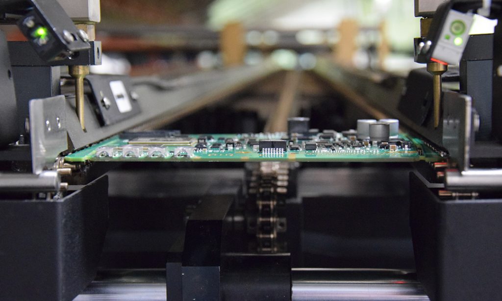
Reflow soldering, also known as reflow welding, is a widely used soldering process in surface-mount technology (SMT) for attaching electronic components onto printed circuit boards (PCBs). The process begins by applying a layer of solder paste onto the contact points on the PCB. This solder paste is a mixture of solder powder and flux, with a viscosity that helps temporarily secure the components in their intended positions. The PCB is then passed through a reflow oven, where the temperature is controlled according to a specific thermal profile. The temperature gradually increases through various stages.
- Preheat: Gradually increase the temperature to avoid thermal shock to the components and PCB.
- Soak: Maintain a stable temperature to activate the flux and remove oxides from the metal surface.
- Reflow: The temperature rises above the melting point of the solder alloy, causing the solder to become liquid and establishing an electrical connection between the component and the PCB.
- Cooling: The temperature drops to cause solidification and welding, creating a durable weld.
The reflow soldering process ensures that components are securely and precisely mounted onto the PCB while minimizing the risk of thermal damage. This method is particularly effective for mass production in the electronics industry.
History of formation and significance
Reflow soldering emerged as an inevitable part of the development of modern electronic technology, especially as surface-mount technology (SMT) began to replace traditional through-hole technology (THT). Around the late 1970s and early 1980s, the electronics industry witnessed a dramatic shift—from bulky components to compact integrated circuits, which demanded precise, uniform assembly techniques capable of mass production. Reflow soldering quickly became the ideal method for meeting these needs.
The reflow soldering process was originally used in the manufacturing of high-end military and industrial equipment, where extremely high reliability was required. However, thanks to continuous improvements in equipment, temperature-control software, and soldering materials, this technology has become increasingly widespread and is now found in most electronic circuit board manufacturing plants—ranging from mobile phones and laptops to industrial control systems.
The greatest significance of this invention lies not only in its ability to efficiently bond components but also in optimizing the manufacturing process: reducing labor costs, enhancing consistency, minimizing technical errors, and improving the quality of the final products. For PCB manufacturers, reflow soldering represents a breakthrough that ushers in an era of automation and high productivity in the electronics industry.
Operating Principle of Reflow Soldering
Overview of the reflow soldering process
Preheat Stage – Primary Heating
The Preheat stage, or primary heating, is the initial step in the reflow soldering process. Its main objective is to gradually and evenly raise the temperature of the printed circuit board (PCB) and components, thereby avoiding thermal shock and preparing for the subsequent soldering steps.
Typically, the temperature rises at a rate of 1.5–3°C per second up to about 150°C. This steady heating rate effectively vaporizes the solvent and moisture in the solder paste while simultaneously activating the flux, thereby enhancing the quality of the solder joint.
If the temperature rises too quickly, components are prone to thermal stress, which can lead to cracking, breakage, or damage. The vigorous evaporation of solvent vapor can also cause tin splashing, affecting soldering quality. Therefore, controlling the rate and temperature during this stage is crucial for an efficient and safe soldering process.
Soak Stage – Temperature Stabilization
Next is the Soak phase, during which the temperature is maintained steadily within the range of 150–200°C for 60–120 seconds. The goal is to ensure uniform temperature distribution across the PCB and components while continuing to activate the soldering flux.
During this stage, the flux acts vigorously, removing oxides from the surface to be soldered and helping to create strong solder joints. Uniform temperature distribution also helps prevent thermal gradients between components of different sizes, reducing the risk of thermal shock and soldering defects such as "tombstoning" or poor wetting.
However, if the soak period is too long or the temperature is too high, the flux may be depleted prematurely, leading to oxidation and soldering defects such as "graping." Therefore, controlling the duration and temperature during the soak phase is crucial.
Reflow Stage – Tin Melting
This is the critical stage, during which solder joints are formed as the solder melts. The temperature reaches its peak—typically between 240–250°C (for lead-free solder)—exceeding the melting point of the solder to establish a bond between the component leads and the pads on the PCB.
The time spent above the liquidus temperature (TAL) ranges from 30 to 90 seconds. If the TAL is too short, the tin will not have enough time to form a strong bond; if it’s too long, numerous intermetallic compounds will form, making the solder joint brittle and prone to fracture.
The peak temperature should be limited to between 20–40°C above the melting point to avoid damaging components. Throughout this process, flux continues to play a crucial role in removing oxides and ensuring good solder adhesion. Strict control of temperature and time guarantees solder joint quality and product reliability.
Cooling Stage – Rapid Cooling
Cooling is the final step in the reflow soldering process, playing a crucial role in shaping and stabilizing the solder joints after the solder has melted during the reflow stage. Once the peak temperature (typically above 240°C) is reached, the PCB board must be cooled rapidly yet under controlled conditions to ensure that the solder solidifies into the correct microstructure.
The goal is to reduce the temperature below 150°C within 30–60 seconds. This process helps tin crystallize into strong, fine-grained solder joints, preventing the formation of large structures—precisely the type of structure that makes solder joints brittle and prone to cracking.
The cooling method commonly uses forced-air fans or convective cool air to control the cooling rate. However, if cooling is too rapid, thermal contraction differences between the component and the PCB can induce mechanical stress, leading to solder joint cracking or PCB warping.
In summary, cooling is not merely a step to reduce temperature; it also directly affects the weld’s durability, aesthetics, and reliability. A properly controlled cooling process helps enhance product quality and reduce defects in mass production.
Factors affecting weld quality
In the reflow soldering process, the quality of solder joints is influenced by various factors. It is essential to understand and control these factors to ensure product performance and reliability. Below are some key factors that affect soldering quality:
- Solder quality
Solder paste plays a crucial role in producing high-quality solder joints. The composition and properties of solder paste—such as tin particle size, viscosity, and oxidation resistance—directly affect the soldering process. Low-quality solder paste can lead to defects like solder bridges, cold solder joints, or insufficient soldering. Therefore, selecting the right solder paste and storing it properly are extremely important.
- Solder paste printing process
Printing solder paste onto PCBs requires high precision. Parameters such as squeegee pressure, printing speed, and stencil design must be tightly controlled. Errors during the printing process can result in insufficient or excessive solder paste, leading to solder joints that fail to meet specifications. According to research, controlling the solder-paste printing process is one of the key factors in ensuring the quality of reflow soldering.
- PCB design and quality
The solder pad design on a PCB must comply with technical standards to ensure proper alignment with the components. Incorrect pad size and shape can lead to issues such as component shift or uneven soldering. Additionally, the PCB surface must be clean, free of dust or oxidation, to ensure good solder paste adhesion and high-quality solder joints.
- Furnace temperature and configuration
The thermal profile in a reflow soldering oven significantly affects the quality of solder joints. Stages such as preheat, soak, reflow, and cooling must be set with appropriate temperatures and durations. Temperatures that are too high or too low, or insufficient time, can lead to defects such as cold solder joints, cracked solder joints, or component damage. Precise control of the thermal profile ensures that the soldering process is carried out efficiently.
- Welding capability of the component
The solderability of components depends on the material and surface condition of the component leads. Oxidized or dirty component leads can result in poor solder joints or failure to establish a connection. Therefore, it is essential to inspect and prepare the surface of component leads before soldering to ensure optimal solderability.
- Operator skills and experience
Operators need to have the knowledge and skills to set up and monitor technical parameters during the welding process. A lack of experience or operational errors can lead to weld quality issues. Therefore, training and skill enhancement for operators are crucial factors in ensuring welding quality.
Applications of Solder Reflow in PCB Manufacturing
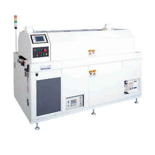
In modern PCB manufacturing lines, reflow soldering technology is primarily used for circuits that employ surface-mount devices (SMDs) rather than through-hole components (THTs). Thanks to its ability to distribute heat evenly and precisely control each thermal stage, reflow soldering has become the optimal solution for securely mounting SMD components, thereby ensuring accuracy, consistency, and minimizing defects during the soldering process. This technology not only enhances product quality but also contributes to the automation of production lines, speeding up manufacturing processes and reducing reliance on manual labor in electronic factories.
Advantages and Disadvantages of Reflow Soldering
Reflow soldering is an important technique in PCB manufacturing, particularly well-suited for surface mount technology (SMT). Below is a summary table of the advantages and disadvantages of this method:
| Advantages | Disadvantages |
| High performance Reflow soldering allows simultaneous soldering of multiple components on a PCB, increasing production speed and efficiency. | High equipment costs Investment in equipment such as reflow soldering ovens and automatic component placement machines is required, resulting in high initial costs. |
| Stable weld quality The heating process is tightly controlled, minimizing the risk of defects such as weld cracks or cold cracks. | Sensitive to temperature Some temperature-sensitive components may be damaged by high temperatures during soldering. |
| Minimize heat shock The gradual heating and cooling process helps minimize thermal shock to the components. | Not suitable for through-hole components (THT) Reflow soldering is primarily used for SMT components; if the PCB contains both through-hole components, an additional soldering step is required. |
| Save welding material Use the exact amount of solder paste needed to minimize material waste. | Strict process control requirements It is necessary to precisely control parameters such as temperature and time to avoid defects like tombstoning or solder bridging. |
| Environmentally friendly Produces less waste and minimizes the use of lead in soldering. | Difficulty in rework Repairing SMT solder joints requires specialized techniques and equipment. |
Summary
Reflow soldering is a modern soldering method that plays a crucial role in the PCB manufacturing process using SMT technology. With its high degree of automation, ability to ensure stable solder joint quality, and optimized production costs, this technology has become the top choice for today's electronics manufacturers. However, to achieve maximum efficiency, companies need to strictly control technical parameters and select solutions that are appropriate for each type of component and production scale.
Contact Us
Contact Number:
+86 21 6088 8500
+86 4006 777 950
+86 150 2686 5822
Email:
marketing@hapoin.com
Headquarter Address:
6, South Metropolis Garden, No. 1165, Jindu Road, Minhang District, Shanghai
OUTLETS
Service Outlets

Shanghai-Head Office
Shanghai Hapoin Enterprise Development Co., Ltd.
Address: Building 6, Southern Metropolis Garden, No. 1165, Jindu Road, Minhang District, Shanghai
Telephone:+86 150 2686 5822
Email:info@hapoin.com
Shenzhen Branch
Shenzhen Hapoin Ruihe Technology Development Co., Ltd.
Address: Room 302, 3rd Floor, Building B, Kaicheng High-tech Park, Dalang Street, Longhua District, Shenzhen
Telephone:+86 755 2223 2285
Email:sales@hapoin.com
Hong Kong Branch
HAPOIN ENTERPISE LIMITED
Address: Unit 917A, 9/F., Tower A, New Mandarin Plaza, No. 14 Science Museum Road
Telephone:+00852 61187991
Email:sales@hapoin.com
Vietnam Branch
HAPOIN VIETNAM
Address: 6th Floor, CTM Office Building, No. 139, Zhipiao Road, Zhipiao District, Hanoi, Vietnam
Telephone:+84 398 848 969
Email:sales@hapoin.com
Japan Branch
HAPOIN CO., LTD.
Address: 6th Floor, 2-3-8 Iwamotocho, Chiyoda-ku, Tokyo
Telephone:+81 070 9356 1267
Email:sales@hapoin.com
Kunshan Office
Kunshan Office
Address: 10th Floor, Building B, Modern Plaza, No. 8, Weiye Road, Yushan Town, Kunshan City
Telephone:+86 150 2686 5822
Email:sales@hapoin.com
Taipei Branch
Uniwin Chemical Co.,LTD.
Address: No. 14, Alley 3, Lane 250, Section 2, Huanhe South Road, Taipei 10853
Telephone:+886 02 2336 2202
Email:sales@hapoin.com
Beijing Office
Beijing Office
Address: Room 306, Building 4, Zhongtou Oriental, West Zhihe North, Chaoyang District, Beijing
Telephone:+86 150 2686 5822
Email:sales@hapoin.com


Contact Number
Headquarter Address
6, South Metropolis Garden, No. 1165, Jindu Road, Minhang District, Shanghai
Follow the official account
Follow the video account

